
Rainscreen Wall Systems: Design and Construction Guide
How rainscreen walls manage rain, drainage, drying, pressure, attachments, openings, fire, insects, installation, and maintenance.
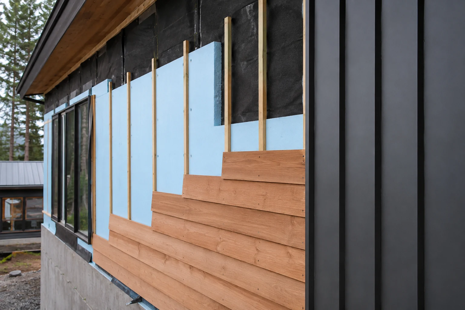
A rainscreen wall separates the exterior cladding from a water-control layer with a defined cavity. The cladding sheds most rain; flashings and the water-resistive barrier manage water that passes it; the cavity provides drainage and may support ventilation and pressure moderation. Performance depends on the entire assembly, not the gap alone.
Key takeaways
- A rainscreen is a water-management approach, not one proprietary product.
- The cavity must connect to flashings and remain open at drainage locations.
- Drained, ventilated, and pressure-equalized systems are not interchangeable terms.
- Furring and clips must transfer cladding loads while controlling corrosion and thermal bridging.
- Openings, penetrations, parapets, decks, and material transitions need buildable details.
- Start with building envelope basics to identify the control layers before selecting cavity products.
This guide is part of the Building Materials library, where envelope strategy, cladding, siding, and wall-system decisions are reviewed together.
What components make a rainscreen wall?
A typical above-grade rainscreen assembly includes exterior cladding, attachments or furring, a cavity, a water-resistive barrier, flashings, sheathing or another substrate, structure, insulation, air control, vapor control when needed, and interior finishes.
One material may perform several functions. A taped exterior sheathing product may provide water and air control. Exterior insulation may provide thermal control and influence drainage. A panel rail may support cladding and create the cavity. Combining functions can simplify work, but only when transitions and installation tolerances are clearly documented.
The cavity does not replace the water-control layer. It creates separation so water can drain and sensitive layers can dry more effectively. It also reduces contact between wet cladding and the wall behind it.
Drained, ventilated, and pressure-equalized systems
| System description | Openings | Main purpose | Design caution |
|---|---|---|---|
| Drained cavity | Drainage openings at the bottom and interruptions | Give liquid water a clear route out | The exit can be blocked by sealant, debris, or finish work |
| Drained and ventilated cavity | Low and high openings or another deliberate airflow path | Support drainage and greater air exchange | Vent locations need insect, ember, and fire review |
| Pressure-moderated or pressure-equalized rainscreen | Compartmented cavity and engineered openings | Reduce pressure difference that drives rain across cladding joints | Requires project-specific engineering and air-barrier continuity |
Many residential walls described as rainscreens are drained or back-ventilated siding systems, not pressure-equalized facades. Precise language helps the design team set the correct expectations for compartmentalization, joint openness, testing, and field tolerances.
How large should the cavity be?
There is no universal cavity dimension. Cladding manufacturer requirements, local code, drainage needs, ventilation intent, attachment geometry, fire provisions, insects, workmanship, and expected debris all affect the choice.
A textured membrane or drainage mat may create a thin capillary break behind some siding systems. Vertical furring creates a more defined drainage space. Masonry veneer, open-joint panels, and engineered commercial facades may require different cavity depths and support systems.
The cavity must remain continuous enough to perform. Horizontal furring can block vertical drainage unless it is interrupted, vented, or installed as part of an engineered grid. Thick insulation, clips, shelf angles, and fire-stopping can divide the cavity and require local drainage at each interruption.
Use the current code, system documentation, and qualified design rather than assuming a dimension from another project.
Design the water-control layer first
The water-resistive barrier should be continuous, properly lapped or sealed, and connected to flashings. The selected product must be compatible with substrates, primers, tapes, sealants, fasteners, and expected ultraviolet exposure during construction.
Trace the water-control layer through a wall section without lifting the pencil. Then repeat the exercise around a window, at the base of wall, at a roof intersection, and where the cladding changes. If the line stops at a drawing break or a note that says “by others,” the transition needs more coordination.
The rainy-climate construction guide explains how wind, exposure, construction moisture, and temporary weather protection influence these details.
Detail the base and top of the cavity
At the base, water needs a flashing or termination that directs it outside while maintaining required clearance from soil, paving, roofing, and horizontal surfaces. Screens or formed closures may exclude insects and debris, but they should not reduce drainage below the system’s requirements.
At the top, the design may close the cavity, vent it, or connect it to another termination depending on the assembly. Parapets, soffits, roof edges, and wall-to-roof conditions must prevent rain entry while maintaining the intended airflow or pressure behavior.
Do not seal the drainage opening during landscaping or finish work. Clearances visible during cladding installation can disappear when paving, decks, insulation, or planting beds are completed.

Integrate windows, doors, and penetrations
Openings concentrate interfaces among structure, water control, air control, insulation, and cladding. The sill should provide a route for incidental water to reach the exterior. Jamb and head details should maintain drainage and avoid directing water into the cavity at vulnerable locations.
Decide whether the window aligns with the structure, sheathing, exterior insulation, or cladding plane. That choice affects sill depth, head flashing, attachment, thermal bridges, interior returns, and construction sequence.
Pipes, ducts, lights, outlets, railings, signs, and equipment should use planned mounting blocks, sleeves, or support assemblies. A late penetration through finished cladding can puncture the water-control layer without access for a reliable repair.
Coordinate attachments and thermal bridging
Cladding dead load, wind pressure and suction, seismic forces, impact, and movement pass through furring, rails, clips, anchors, and fasteners. Attachment spacing should come from the cladding system, substrate, building geometry, and engineering requirements rather than habit.
Fasteners through exterior insulation can create thermal bridges and may impose bending or compression on the insulation. Clip-and-rail systems can reduce some bridging but add cost, components, tolerances, and corrosion interfaces.
The design team should review fastener material, coating, edge distance, embedment, substrate capacity, pull-out values, adjustment, and compatibility with treated wood or dissimilar metals. Coastal exposure requires added attention; see the coastal construction materials guide.
Match the cavity to the cladding
Lap siding, shingles, board-and-batten, panels, stucco, masonry veneer, and thin adhered finishes do not use the same attachment or drainage strategy. Some systems are installed over vertical furring. Others need crossed rails, drainage mats, lath, shelf angles, or proprietary clips.
Open-joint cladding exposes the layer behind it to more ultraviolet light and direct water. The visible membrane or panel must be approved for that exposure, and joint geometry must match the intended appearance and water strategy.
Reservoir claddings can absorb and store water. Separation helps reduce contact with sensitive layers and increases drying potential. Use the exterior cladding guide and Pacific Northwest siding comparison to compare material behavior.
Address fire, insects, and wildlife
Cavities can move air and may also provide paths for flame, smoke, embers, insects, and small animals. Requirements vary by building type, height, cavity geometry, materials, jurisdiction, and wildfire context.
Fire blocking or cavity barriers can interrupt drainage and ventilation if added without enclosure coordination. Each barrier location needs a detail that maintains water management. Vent screens must balance opening area with insect and ember resistance where applicable.
Do not assume that a noncombustible cladding makes the entire wall noncombustible or ignition-resistant. Membranes, insulation, furring, attachments, openings, and adjacent site conditions remain part of the assessment.
Plan installation and quality assurance
Use a preinstallation meeting to review substrate tolerances, membrane repairs, furring layout, fasteners, flashings, opening details, cavity closures, trade sequencing, and testing. Build a representative mockup before production work.
Inspect the water-control layer before furring hides it. Mark repairs using compatible materials. Observe fastener type and spacing, attachment to structure, cavity continuity, flashing slopes, screen placement, and clear drainage exits.
Water testing may be appropriate for higher-risk assemblies, but the team should agree on the procedure, specimen, timing, acceptance criteria, and repair process before testing starts. Random spraying without a defined pressure or observation method does not establish performance.

Can an existing wall be converted to a rainscreen?
Re-siding creates an opportunity to add drainage space, exterior insulation, improved flashing, and better air sealing. The existing wall should first be investigated for leakage, decay, hazardous materials, structural capacity, and compatibility.
Adding thickness changes window and door returns, roof and deck interfaces, utility penetrations, property-line clearances, and attachment lengths. The retrofit should connect to the foundation and roof water-control systems rather than stopping at the field of wall.
Rainscreen checklist
- Identify the intended system as drained, ventilated, or pressure-moderated
- Name the water, air, vapor, and thermal control layers
- Confirm cavity depth and continuity
- Detail base, top, openings, penetrations, and interruptions
- Coordinate cladding load paths and fasteners
- Review corrosion and dissimilar-metal contact
- Resolve fire, insect, ember, and wildlife requirements
- Verify membrane exposure and product compatibility
- Build and document a representative mockup
- Inspect before concealment and keep drainage exits open
- Provide maintenance access and closeout records
Common questions
Is a rainscreen required everywhere in the Pacific Northwest?
Requirements depend on jurisdiction, exposure, cladding, and assembly. A drained space is often a sound durability measure in wet regions, but its design must match the project rather than a regional slogan.
Does a rainscreen stop all rain before it reaches the WRB?
No. The cladding reduces direct rain, while the cavity and water-control layer manage water that passes the exterior surface. Open-joint systems may intentionally expose the layer behind the cladding to more water.
Must a rainscreen cavity be ventilated at the top?
Not always. Some systems are drained at the bottom, some are vented at top and bottom, and pressure-equalized systems use engineered openings and compartments. Follow the designed system and current requirements.
Can horizontal furring be used?
It can be part of a designed attachment system, but continuous horizontal members may block drainage. The layout needs a deliberate vertical water path and coordination with ventilation, fire barriers, and structural support.
Sources and limitations
This guide was reviewed against the DOE Building America drainage-plane guide, the DOE guide to flashing at the bottom of walls, the Whole Building Design Guide moisture resources, and the U.S. Army Corps of Engineers building-envelope quality assurance guide.
Rainscreen terminology and requirements vary. Project-specific structural, fire, moisture, energy, and code decisions should be made by qualified professionals using current documents.
Related articles
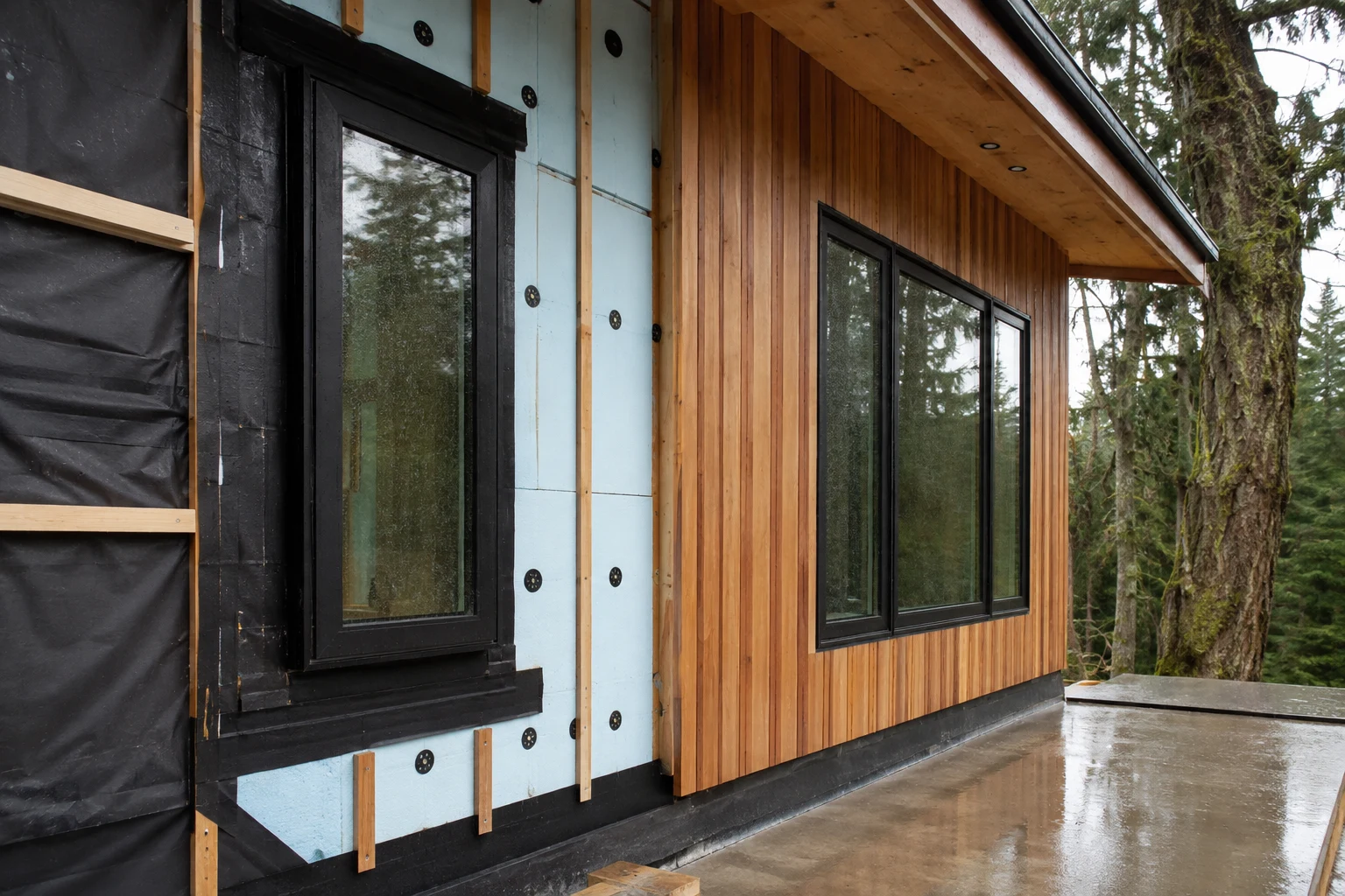
Building Envelope Basics for West Coast Projects
A clear guide to water, air, vapor, and thermal control layers, plus the transitions that determine wall and roof durability.
Read article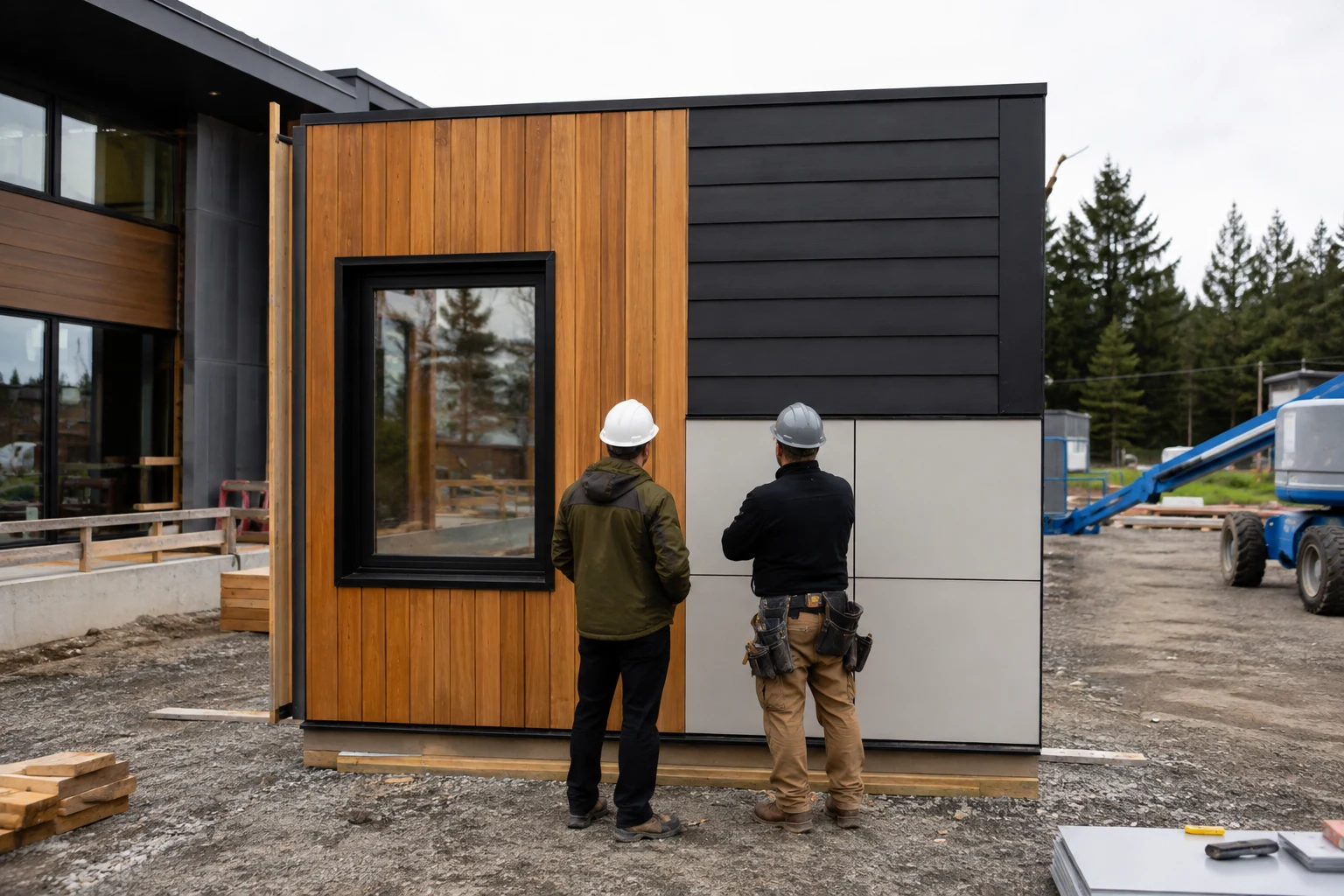
Exterior Cladding Guide for West Coast Buildings
How to compare exterior cladding by climate exposure, drainage, structure, fire context, installation, maintenance, repairability, and total project fit.
Read article
Best Siding for Pacific Northwest Homes
A practical comparison of wood, engineered wood, fiber cement, vinyl, metal, stucco, and masonry siding for Pacific Northwest conditions.
Read article